Datacenter
NTP and PTP design guide for Nexus 9000 NDFC fabrics
Overview
This guide describes a time-synchronization design for Cisco Nexus 9000 leaf-spine VXLAN EVPN fabrics managed by Cisco Nexus Dashboard Fabric Controller (NDFC).
It uses two complementary services:
- NTP provides millisecond-accurate system-clock time for the management plane, including syslog, AAA, certificate validation, and
showcommand output. - PTP (IEEE 1588) provides sub-microsecond hardware-clock synchronization for data-plane timestamping and flow telemetry.
NTP and PTP run at the same time. NTP disciplines the grandmaster system clock, and ptp clock periodic-update transfers that time to the grandmaster hardware clock. The hardware clock then distributes time through the PTP domain. This removes the requirement for an external GNSS/PTP grandmaster where NTP meets the design’s absolute-time requirements.
Out of scope
GNSS deployment, SyncE, telecom G.8275.x profiles, and WAN time distribution are outside the scope of this guide.
The two clocks in a Nexus switch
A Nexus 9000 has two independent clocks.
| Clock | Disciplined by | Accuracy class | Used by |
|---|---|---|---|
| System clock (RTC) | NTP on the grandmaster, PTP on downstream switches, or manual configuration | Milliseconds | Syslog, SNMP, AAA, certificates, show clock |
| Hardware clock (ASIC) | PTP | Sub-microsecond | Packet timestamping, NDFC flow telemetry, PTP distribution |
The protocols do not conflict because they discipline different clocks. NX-OS clock management decides which protocol controls the system clock.
Target clock flow
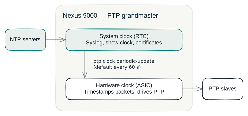
- NTP sets the absolute wall-clock time on the grandmaster system clock.
ptp clock periodic-updatecopies that system-clock time to the grandmaster hardware clock.- The hardware clock distributes precise relative time to the rest of the PTP domain.
PTP gives switches close agreement with each other. Absolute accuracy remains limited by the NTP source.
Network Time Protocol
Role in this design
NTP disciplines the grandmaster system clock and remains configured as a backup on downstream switches. Logs, AAA records, and certificate checks can then use a common, trustworthy time reference.
Key properties
- NTP is software based and does not use hardware timestamping. On a LAN, it commonly achieves single-digit millisecond accuracy.
- NTP uses a hierarchical stratum model. A stratum-16 clock is unsynchronized and free-running.
- Local oscillators can drift by approximately +/-100 ppm, so clocks need continuous discipline.
Design parameters
| Parameter | Value |
|---|---|
| NTP server(s) | ntp1.example.net, ntp2.example.net, ntp3.example.net |
| VRF for NTP | management |
| Source interface | mgmt0 |
Example configuration
Use this NTP client block on the grandmaster and on downstream switches. Replace the placeholder hostnames with approved time sources for the target environment.
logging level ntp 4
ntp server ntp1.example.net use-vrf management
ntp server ntp2.example.net use-vrf management
ntp server ntp3.example.net use-vrf management
ntp source-interface mgmt0
Precision Time Protocol
Role in this design
PTP disciplines the hardware clock and distributes precise time through the fabric. NDFC flow telemetry uses this consistency to correlate hardware timestamps from different switches.
Clock roles on Nexus 9000
- Nexus 9000 switches operate as boundary clocks by default.
- A boundary clock can also act as a grandmaster when it has a disciplined time source.
- Nexus 9000 does not support the transparent-clock role.
Key parameters
| Parameter | Value |
|---|---|
| PTP profile | Default IEEE 1588 |
| PTP domain | 0 |
| Transport mode | Multicast over routed fabric links |
| PTP source IP | A unique loopback address for each switch |
| Operation | Two-step |
| Correction range | 10000 ns notification threshold |
Base configuration
Apply the base PTP configuration to switches that participate in the PTP domain. Each switch must use its own loopback address. The examples in this guide use the private documentation range 10.1.1.0/24.
feature ptp
ptp source <unique-loopback-ip>
ptp notification type parent-change
ptp notification type gm-change
ptp notification type high-correction interval 20 periodic-notification enable
ptp notification type port-state-change category all
ptp correction-range 10000

interface Ethernet1/<n>
  ptp
Both example devices use PTP domain 0, the NX-OS default. Confirm the effective setting with show ptp clock.
Timestamp tagging and ttag-strip
PTP always disciplines the hardware clock. On downstream switches that use clock protocol ptp, PTP also supplies time to the system clock. PTP does not add timestamps to application traffic by itself.
TTAG uses the PTP-disciplined hardware clock on the data plane. When configured on an interface, the ingress ASIC adds a trailer containing a hardware timestamp. Flow telemetry can use that data to measure per-hop and end-to-end latency with nanosecond resolution.
ttag-strip removes the trailer before the frame leaves an interface. Use it on a path that leads to an endpoint or any device that does not understand TTAG.
Port roles
TTAG and PTP apply to different port roles.
| Port role | ptp |
ttag / ttag-strip |
Example |
|---|---|---|---|
| Inter-switch fabric link | Yes | No | Grandmaster-1 Ethernet1/1 to Leaf-1 Ethernet1/36 |
| Host, edge, or access port | No | Yes, both | Server-facing interfaces |
PTP carries time over a fabric link. TTAG must remain intact while traffic crosses the instrumented fabric. On a host-facing port, ttag adds the ingress timestamp and ttag-strip removes it before the endpoint receives the frame.
interface Ethernet1/<n>
  ttag
  ttag-strip
  mtu 9216
  no shutdown
An interface is either a PTP fabric link or a TTAG host-facing port. Do not configure both roles on the same interface.
Clock manager behavior
NX-OS clock management selects the protocol that controls the system clock. The clock protocol command does not control the PTP hardware clock.
| Setting | Meaning |
|---|---|
clock protocol ntp |
NTP controls the system clock. Use this on the grandmaster. |
clock protocol ptp |
PTP-recovered time controls the system clock. Use this on downstream switches. |
clock protocol none |
Only manual configuration can set the system clock. |
This design uses NTP for system-clock ownership on the grandmaster and PTP on every downstream switch.
- The grandmaster uses the NX-OS default
clock protocol ntp.ptp clock periodic-updatethen copies NTP-disciplined system time to its hardware clock. - Downstream spines, leaves, and boundary clocks use
clock protocol ptp. Their system clocks follow the grandmaster through PTP instead of separate NTP sessions.
NTP remains configured on every switch as a fallback and to discipline the grandmaster. On a downstream switch, show ntp peer-status reports INFO: System clock is not controlled by NTP in this VDC. That result is expected when clock protocol ptp is configured.
Fabric design model
Topology
                 [Grandmaster role]
                  Spine-1     Spine-2
                    |  \      /  |
                    |   \    /   |
                    |    \  /    |
          +---------+-----X------+---------+
        Leaf-1    Leaf-2       Leaf-3    Leaf-N
        (BC)      (BC)         (BC)      (BC)
Role assignment
| Fabric role | PTP role | Clock protocol | periodic-update |
Notes |
|---|---|---|---|---|
| Grandmaster | Boundary clock and GM | ntp (NX-OS default) |
Yes | priority1 1, priority2 1, NTP-disciplined |
| Non-GM spine | Boundary clock | ptp |
No | System clock follows the GM through PTP |
| Leaf | Boundary clock | ptp |
No | Priorities remain at the default of 255 |
Choose a deterministic grandmaster position in every fabric. In this example, Grandmaster-1 uses priority1 1 and the default clock protocol ntp. Leaf-1 uses clock protocol ptp and synchronizes to the grandmaster through its upstream fabric link. Each switch has a unique PTP source loopback.
Configure PTP through NDFC fabric settings or policy templates where that is available. Avoid unmanaged, per-switch configuration drift.
Role-based configuration
Validate configuration against the deployed NX-OS release, platform support, and NDFC templates before applying it to a production fabric.
All PTP switches
logging level ntp 4
ntp server ntp1.example.net use-vrf management
ntp server ntp2.example.net use-vrf management
ntp server ntp3.example.net use-vrf management
ntp source-interface mgmt0

feature ptp
ptp source <unique-loopback-ip>
ptp notification type parent-change
ptp notification type gm-change
ptp notification type high-correction interval 20 periodic-notification enable
ptp notification type port-state-change category all
ptp correction-range 10000

interface Ethernet1/<n>
  ptp
Grandmaster additions
ptp priority1 1
ptp priority2 1
ptp clock periodic-update
The grandmaster uses the default clock protocol ntp; an explicit clock protocol line is not required.
The following fabric-link example uses documentation addresses from 10.1.1.0/24.
interface Ethernet1/1
  description connected-to-Leaf-1-Ethernet1/36
  ptp
  mtu 9216
  ip address 10.1.1.33/30
  ip ospf network point-to-point
  ip router ospf UNDERLAY area 0.0.0.0
  ip pim sparse-mode
  no shutdown
Use ttag and ttag-strip, rather than ptp, on a host-facing port.
interface Ethernet1/13
  ttag
  ttag-strip
  mtu 9216
  no shutdown
Non-grandmaster spine
Use only the common NTP and PTP baseline. Do not configure ptp clock periodic-update, priority1, or priority2; the default priority remains 255.
Leaf or PTP slave
clock protocol ptp vdc 1
ptp source 10.1.1.20
The switch retains the base configuration. It uses the default priority of 255 and does not use ptp clock periodic-update.
interface Ethernet1/36
  description connected-to-Grandmaster-1-Ethernet1/1
  ptp
  mtu 9216
  port-type fabric
  ip address 10.1.1.34/30
  ip ospf network point-to-point
  ip router ospf UNDERLAY area 0.0.0.0
  ip pim sparse-mode
  no shutdown
The ptp clock periodic-update mechanism
On a grandmaster without an upstream PTP source, the hardware clock would otherwise free-run on its local oscillator. ptp clock periodic-update periodically copies the NTP-disciplined system clock to the PTP hardware clock. The switch can then act as a grandmaster without external GNSS/PTP input.
| Property | Detail |
|---|---|
| Default interval | 60 seconds |
| Configurable range | 0-3600 seconds |
| Direction | System clock to hardware clock only |
| Behavior | NX-OS ignores it when any port is a PTP slave |
Configure periodic update only on the grandmaster. A grandmaster with only PTP master ports has no other source to discipline its hardware clock. Downstream boundary clocks already synchronize their hardware clocks through a PTP slave port. Copying millisecond-accurate NTP time to that clock would degrade the more precise PTP synchronization, which is why NX-OS ignores the command when a slave port exists.
Grandmaster selection and BMCA priorities
The Best Master Clock Algorithm (BMCA) elects the grandmaster from announced parameters. Lower values win.
| Parameter | Range | Design value |
|---|---|---|
priority1 |
0-255 | 1 on the designated grandmaster; default 255 elsewhere |
priority2 |
0-255 | 1 on the designated grandmaster; default 255 elsewhere |
| Unset priority | 255 | All non-grandmaster switches |
Assign low priority1 values to designated grandmasters. When using redundant grandmasters, use distinct values such as 1 and 2. Leave all other switches at 255 so that BMCA selection is predictable.
Behavior without NTP or PTP
If neither protocol disciplines a clock, it free-runs.
| Clock | Source at boot | Ongoing discipline | Drift |
|---|---|---|---|
| System clock | Battery-backed RTC or manual clock set |
None | About seconds per day, accumulating over time |
| Hardware clock | ASIC initialization | None | No useful wall-clock meaning |
A crystal oscillator that drifts by approximately +/-100 ppm can drift about 8.6 seconds per day. Clock management can still keep ASICs within a single chassis mutually consistent for internal latency measurement, but it cannot align time between chassis. Use clock protocol none only for lab or bring-up cases that require manual time configuration.
Even switches without a PTP requirement should use NTP so their logs, AAA records, and certificate validation have trustworthy timestamps.
Verification and troubleshooting
System clock and NTP
show clock
show ntp peer-status
show ntp authentication-status
show system internal clk_mgr info all
On the grandmaster, expect show clock to report NTP as the time source and show system internal clk_mgr info all to report Clock Protocol : NTP.
Example grandmaster NTP status, using redacted documentation addresses:
    remote               local            st  poll  reach  delay    vrf
----------------------------------------------------------------------------
*10.1.1.201          10.1.1.100       1   64    377    0.00072  management
=10.1.1.202          10.1.1.100       2   64    377    0.03902  management
=10.1.1.203          10.1.1.100       1   64    377    0.00032  management
On a PTP downstream switch, show ntp peer-status can report that NTP does not control the system clock. That result matches the configured clock protocol ptp role.
PTP and hardware clock
show ptp brief
show ptp clock
show ptp parent
show ptp corrections
show ptp counters interface <if>
Example grandmaster clock output:
PTP Device Type : boundary-clock
PTP Source IPv4 Address : 10.1.1.10
Clock Identity : <redacted>
Clock Domain: 0
Priority1 : 1
Priority2 : 1
Steps removed : 0
PTP Clock status  : Holdover
Example downstream clock output:
PTP Device Type : boundary-clock
PTP Source IPv4 Address : 10.1.1.20
Clock Identity : <redacted>
Clock Domain: 0
Priority1 : 255
Priority2 : 255
Offset From Master : 24
Mean Path Delay : 528
Steps removed : 1
PTP Clock status  : Phase Locked
An upstream port on the downstream switch should enter Slave state. Fabric ports facing downstream devices normally enter Master state.
Port       State
---------  --------
Eth1/33    Master
Eth1/34    Master
Eth1/35    Master
Eth1/36    Slave
TTAG
show run interface <if>
show run | include ttag
Expect ttag and ttag-strip on host, edge, and access ports, not on inter-switch PTP links. Treat telemetry timestamps as valid only after show ptp clock reports Phase Locked on downstream switches and Holdover on the NTP-fed grandmaster.
Common checks
| Symptom | Check |
|---|---|
| Both ends show Master | Confirm the PTP domain and run show system internal ptp trouble-shooting interface <if>. |
| Persistent high corrections | Check path stability toward the grandmaster and look for PTP message drops. |
| Unexpected grandmaster election | Verify priority1 values and confirm periodic update is limited to the intended grandmaster. |
| Grandmaster logs are out of sync | Confirm NTP reachability and the default clock protocol ntp. |
| Downstream logs are out of sync | Confirm clock protocol ptp and a locked PTP slave port. |
| Telemetry timestamps are missing | Confirm ttag and ttag-strip on host-facing ports and a locked PTP clock. |
Design recommendations
- Configure the NTP client on every switch. The grandmaster uses
clock protocol ntp; downstream switches useclock protocol ptp. - Run PTP boundary clocks on all fabric switches that provide flow telemetry.
- Use
ttagandttag-stripon host-facing ports, not on inter-switch PTP links. - Configure
ptp clock periodic-updateonly on designated grandmasters. - Set low, distinct BMCA priorities for grandmasters and leave non-grandmasters at the default of 255.
- Validate control-plane policing, platform capabilities, and software support at the intended scale.
References
- Cisco Nexus 9000 Clock Management white paper
- Cisco Nexus 9000 Series NX-OS System Management Configuration Guide, NTP and PTP chapters
- Cisco Nexus 9000 Verified Scalability Guide
- Cisco support documentation for Precision Time Protocol on Nexus 9000
- Cisco NDFC and Nexus Dashboard documentation
Comments & reactions
Sign in with GitHub to leave a comment or reaction.